- Hotline: 0909 981 890

THERMODYNAMIC STEAM TRAP - HOW IT WORKS
|
|
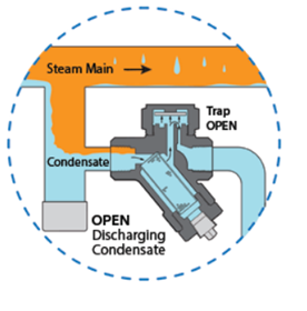
Thermodynamic Steam Trap Thermodynamic traps have only one moving part, the valve disc, which allows condensate to be discharged when present and closes tightly upon the arrival of steam. These traps have an inherently rugged design and are commonly used as drip traps on steam mains and supply lines. Their solid construction and single moving part make them resistant to waterhammer and are freeze-proof when installed vertically. Thermodynamic traps will only discharge small amounts of air and therefore are typically not used in process applications |
|
|
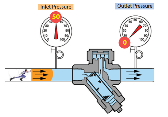
Valve Disc Open
When condensate is present, trap remains in the open position allowing condensate to discharge. Steam pressure pushes the condensate thru the trap. |
|
|
Valve Disc Starting to Close When steam enters the trap, it creates an internal pressure above the disc that instantly forces the disc and seat to close tightly, preventing steam from escaping. |
|
|
Valve Disc Closed Steam pressure above the disc holds the disc closed, trapping steam in the system. Trap will remain closed until the steam above the disc condenses, due to heat loss through the cap. |


Related posts
-
![SATURATED STEAM TABLE]()
-
![]()
-
![Valve leakage]()
-
![WHAT IS STEAM ?]()
-
![CEFI STEAM TRAP]()
-
![]()
-
![WHY USE STEAM?]()
There are three main forms of energy used in industrial processes: electricity, direct heat, and steam.
-
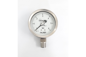
![STRUCTURE OF PRESSURE GAUGE]()
Pressure display dial: Displays measured value and pressure unit. 2. Dial: Indicates the pressure inside the system and the display dial. 3. Bourdon tube: Expands according to the pressure inside the system. 4. Connection: Connection between the system to be measured with pressure gauge. 5. Link: Converts the elastic state of the bourdon tube into the rotation of the clock hands. 6. Screws: Use to fix the display face. 7. Case: Protects the mechanical structure inside the watch. 8. Protector: Transparent glass or plastic material to protect the pressure display dial. 9. Gasket: Seals between the housing and the guard. 10. Mounting Ring: Mount between the pressure display dial and the guard face. 11. Seal: Used to fill oil for the purpose of reducing the movement speed of the internal mechanical mechanism, during operation. It is necessary to cut the small knob above so that there is no condensation, pressure inside the watch during operation.

Copyright © 2020 Technical TL +