- Hotline: 0909 981 890


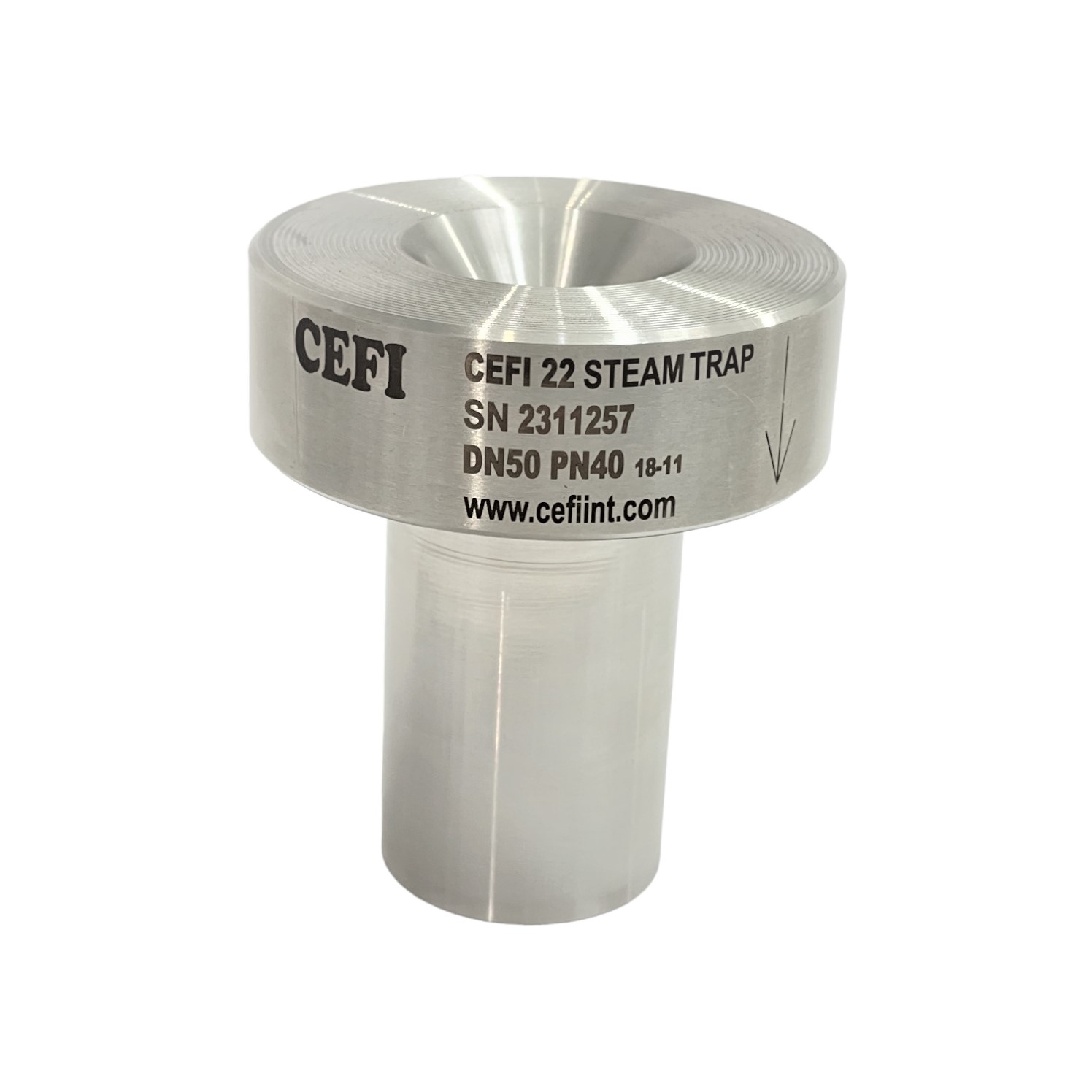
OUR PRODUCTS We Serve The Best Solutions

TECHNICAL


WHY USE STEAM?
There are three main forms of energy used in industrial processes: electricity, direct heat, and steam.

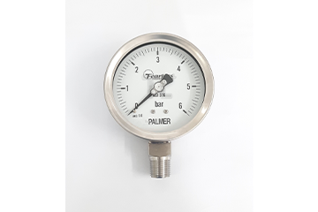
STRUCTURE OF PRESSURE GAUGE
Pressure display dial: Displays measured value and pressure unit. 2. Dial: Indicates the pressure inside the system and the display dial. 3. Bourdon tube: Expands according to the pressure inside the system. 4. Connection: Connection between the system to be measured with pressure gauge. 5. Link: Converts the elastic state of the bourdon tube into the rotation of the clock hands. 6. Screws: Use to fix the display face. 7. Case: Protects the mechanical structure inside the watch. 8. Protector: Transparent glass or plastic material to protect the pressure display dial. 9. Gasket: Seals between the housing and the guard. 10. Mounting Ring: Mount between the pressure display dial and the guard face. 11. Seal: Used to fill oil for the purpose of reducing the movement speed of the internal mechanical mechanism, during operation. It is necessary to cut the small knob above so that there is no condensation, pressure inside the watch during operation.


Copyright © 2020 Technical TL +